A new motherboard, a case, and a pile of cables can become a working computer in under an hour, or a machine that powers on to a black screen and stays there. The difference is rarely luck. Motherboard installation is a fixed sequence of small steps, and nearly every failed first boot traces back to one of them skipped or done out of order: a forgotten CPU power cable, a stray standoff grounding the board, a front-panel connector on the wrong pins. Learn the sequence once, and the black-screen mysteries mostly disappear.
CompTIA A+ Core 1 (220-1201) covers this under objective 3.5, which asks you, given a scenario, to install and configure motherboards. The verb matters: this objective is the hands-on procedure, not picking a compatible board. Scenario questions test the order of operations and what stops a system from completing the power-on self-test (POST) on first boot. Here is the master sequence to know from memory:
- Read the motherboard manual, verify the form factor fits the case, and set up an anti-static workspace.
- If replacing an existing board, photograph and label every connection before removing anything.
- Install the CPU, the CPU cooler, and the RAM on the board while it's outside the case.
- Snap the input/output (I/O) shield into the case opening, unless the board has an integrated shield.
- Install standoffs to match the board's screw holes exactly, and remove any extras.
- Lower the board onto the standoffs, press it against the I/O shield, and screw it down evenly.
- Connect the front-panel headers using the map in the manual.
- Connect the 24-pin main power and the 4/8-pin CPU power.
- Plug the CPU cooler into the CPU fan header and connect the case fans.
- Tidy the cables, then run the first power-on checklist: POST, firmware setup, component detection, boot order, temperatures.
Preparation prevents most motherboard installation mistakes
Before a screw turns, read the motherboard manual. You'll return to it three or four times during the install: it maps the front-panel header, the fan headers, and the power connectors. Older boards sometimes needed physical jumper changes; modern boards handle configuration in firmware setup, but the manual tells you either way.
Next, confirm the board physically fits. Form factors, chiefly ATX (Advanced Technology eXtended), microATX, and Mini-ITX, define the board's dimensions and mounting-hole pattern. Most ATX cases also accept the smaller boards because the hole patterns overlap; the reverse never works. Verify this before the build starts.
Then set up the workspace: a Phillips screwdriver, good lighting, a clean flat surface, and protection against electrostatic discharge (ESD). A static shock too small to feel can kill a component outright or weaken it so it fails weeks later. Wear an anti-static wrist strap clipped to unpainted case metal, work on a hard surface rather than carpet, keep the board in its anti-static bag until needed, and handle it by the edges. For the exam, associate motherboard handling with an ESD strap and an anti-static surface automatically; it's a favorite answer choice.
Install the CPU, cooler, and RAM before the board goes into the case
This is the most tested procedural fact in the objective: populate the motherboard before you mount it. Install the central processing unit (CPU), the cooler, and the memory while the board lies flat on an anti-static mat or its box.
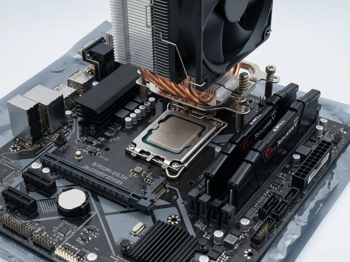
The reason is access and leverage. Seating a CPU means aligning the chip precisely under a retention arm. Mounting a cooler means pressing fasteners or screwing a bracket down against real resistance. Seating RAM takes firm pressure until the clips snap. Each of those actions is awkward once the board stands vertically in a case, and pressing hard on a board supported only by standoffs can flex it enough to crack a trace, an invisible, unrepairable fault. On the open bench, the board is fully supported and you press straight down.
Many technicians also bench-test at this stage, connecting just the power supply and one RAM stick to confirm the board POSTs before it enters the case. If a scenario asks what to do before securing the motherboard in the case, the answer is install the CPU, cooler, and memory.
The I/O shield snaps in first, and it only fits one way
The I/O shield is the thin metal plate with cutouts for the rear ports: USB (Universal Serial Bus), video, audio, and network. It closes the gap around the ports against dust and airflow leaks, provides electromagnetic shielding, and grounds the port housings through small metal fingers.
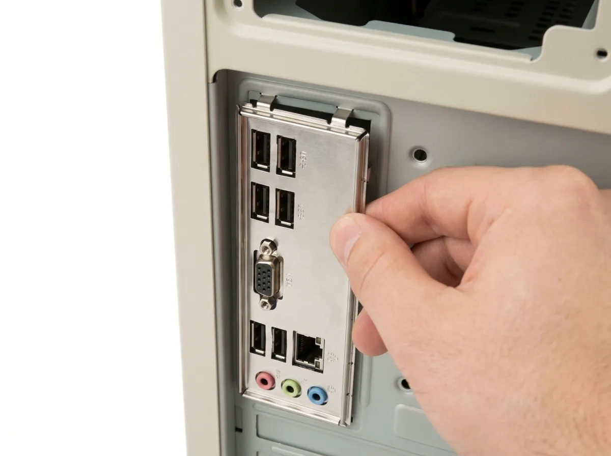
Install it before the motherboard, because it snaps into the case's rear opening from the inside; once the board is mounted, the shield can't go in without removing the board again. Forgetting it is a rite of passage nearly every technician discovers after everything is cabled. Orient it to match the port layout, press until all edges click, and check that no grounding finger will intrude into a port opening when the board slides in; a finger jammed inside a USB port can block or short the port.
Many newer boards ship with an integrated I/O shield permanently attached, which removes this failure mode entirely: the shield seats into the opening as you position the board. Know both patterns for the exam.
Standoffs must match the board's screw holes, and a stray one shorts the board
Standoffs are small threaded posts, usually brass, that screw into the case's motherboard tray and hold the board a few millimeters off the metal. They are the mechanical support the board screws into, and the insulation gap: the board's underside is covered with exposed solder points, and the tray is grounded steel.
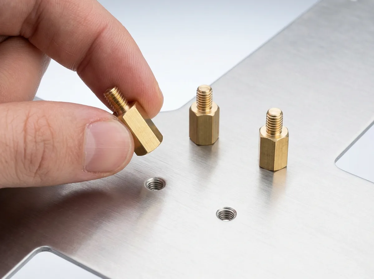
The rule is exact matching — every standoff must line up with a screw hole in the board, no more and no fewer. Hold the board over the tray and note which threaded positions align with its holes; cases include extra positions for multiple form factors, so some stay empty. Install standoffs in the matching spots, and remove any pre-installed ones that don't line up with a hole.
That removal is the critical check. A stray standoff with no hole above it presses its metal top against the board's soldered underside and shorts it to ground. The classic symptoms: the system refuses to power on, powers on for a second and shuts off, or behaves erratically like a dead board.