Structured cabling is an organized system for connecting computers, switches, access points, printers, phones, and other network devices within a building. Instead of running a separate cable directly from every computer to a network switch, structured cabling uses permanent cable runs, wall jacks, patch panels, equipment racks, and short patch cables.
A properly installed structured cabling system makes a network easier to expand, troubleshoot, document, and maintain. CompTIA A+ technicians should understand how a physical network connection travels through a building and how each cabling component contributes to the overall network.
Patch Panels and Structured Cabling
A patch panel is a networking component that provides a central termination point for permanent network cable runs. Patch panels are commonly mounted inside a network rack or telecommunications closet near the network switches.
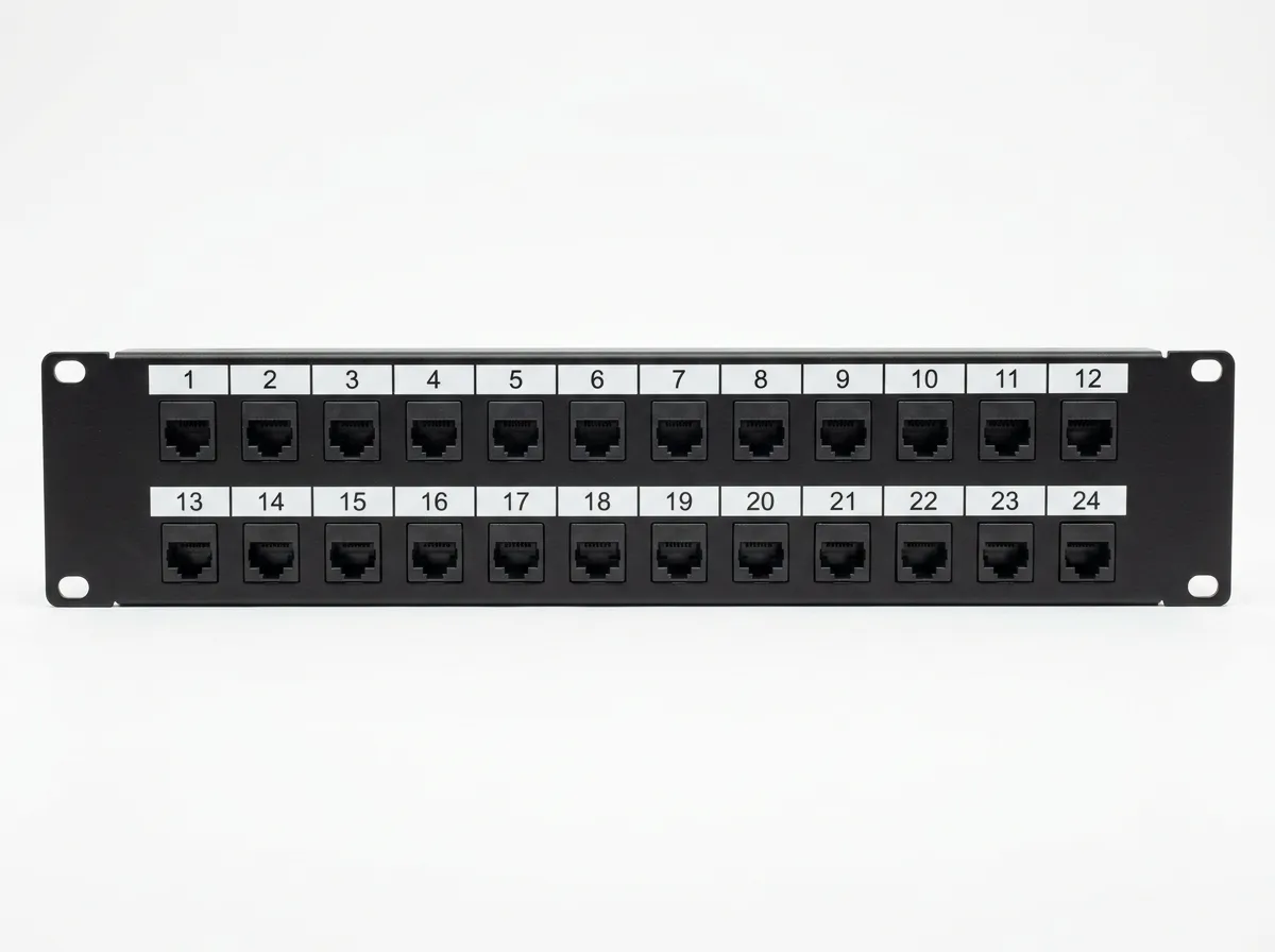
Ethernet cables installed inside walls and ceilings are known as permanent cable runs or horizontal cabling. One end of each permanent cable normally terminates at a wall jack in an office, classroom, or work area. The other end terminates on the rear of a patch panel.
The individual conductors inside the Ethernet cable are connected to insulation displacement connectors, also called IDC terminals. A punchdown tool is used to press each conductor into the correct terminal according to the T568A or T568B wiring standard.
The front of the patch panel contains numbered RJ45 ports. Each port corresponds to a permanent cable run somewhere in the building. For example, a patch-panel port may connect to a specific wall jack in an office or classroom.
A patch panel does not create network connectivity by itself. It is a passive device and does not forward Ethernet frames, assign IP addresses, or provide network services. A short Ethernet patch cable must connect the patch-panel port to an active switch port.
The connection inside the network rack follows this path:
Patch panel → patch cable → switch
Patch panels allow permanent building cabling to remain stationary. Technicians can connect, disconnect, or rearrange network services by moving short patch cables instead of repeatedly handling the permanent cables inside the walls.
This reduces cable damage and makes network changes easier. For example, if a wall jack needs to be connected to a different switch port, the technician can move the patch cable inside the network rack without replacing the horizontal cable.
CompTIA A+ technicians may need to identify patch panels, trace connections through them, replace patch cables, check port labels, or determine whether a network problem exists between a wall jack and a switch.
Following the Physical Network Path
When troubleshooting a wired network connection, a technician should understand the complete physical path between the endpoint device and the network switch.
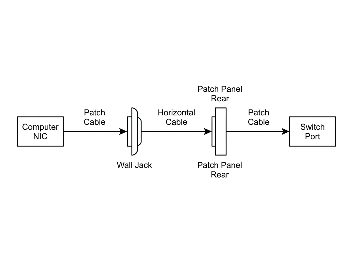
A typical connection follows this path:
Computer → patch cable → wall jack → horizontal cable → patch panel → patch cable → switch
Computer
The computer or endpoint device contains a network interface card, commonly called a NIC. The NIC provides the Ethernet port used to connect the device to the wired network.
Patch Cable
A short Ethernet patch cable connects the computer’s NIC to the wall jack. Patch cables normally use stranded conductors because they are flexible and are designed to be moved or replaced.
If the computer does not have a network connection, the technician should verify that the patch cable is securely connected. The cable should also be inspected for broken locking tabs, damaged connectors, cuts, crushing, or excessive twisting.
Wall Jack
The wall jack provides the user-accessible network connection in the room. The front normally contains an RJ45 Ethernet port. The cable connected to the rear of the wall jack continues through the wall or ceiling toward the network closet.
Wall jacks should be clearly labeled so technicians can identify the corresponding patch-panel port.
Horizontal Cable
Horizontal cabling is the permanent Ethernet cable installed between the work area and the telecommunications room. It is typically solid-conductor twisted-pair cable, such as Cat 5e, Cat 6, or Cat 6A.
Horizontal cable is not normally plugged directly into a computer or switch. Instead, it terminates at a wall jack on one end and a patch panel on the other.
Because horizontal cable is part of the building’s permanent infrastructure, it should not be repeatedly bent, moved, or disconnected.
Patch Panel
The horizontal cable terminates at the rear of a patch-panel port. The corresponding port on the front of the panel provides an RJ45 connection.
A technician can use the labels on the wall jack and patch panel to locate the correct cable run. A cable tester or toner probe may also be used when labels are missing or incorrect.
Patch Cable to the Switch
A short patch cable connects the front of the patch panel to a port on the network switch.