Open almost any desktop and you'll find one thick bundle of wires running from the power supply to the motherboard, ending in the widest connector in the case. That's the main power connector, and on modern systems it's a 24-pin plug built as a 20-pin block with a detachable 4-pin piece. Knowing why it's split that way tells you a lot about how PC power has evolved.
CompTIA A+ Core 1 (220-1201) Objective 3.6 covers power supplies, and the main motherboard connector is one of the specific items you're expected to recognize and describe. In exam terms, you should be able to identify the 20+4 pin connector on sight, explain what the extra four pins add, and know how it differs from the separate CPU power connector that looks similar but isn't the same thing.
This article stays on what a technician actually checks: the connector's layout, the voltages it carries, why it separates into two pieces, and the seating and compatibility mistakes that cause dead or unstable systems.
The main connector feeds the whole board, not just the CPU
The 20+4 pin connector is the primary power feed from the power supply unit (PSU) to the motherboard. Everything that draws power through the board relies on it, including the chipset, RAM slots, PCIe slots, onboard controllers, and the front-panel circuitry. When this connector isn't seated fully, the system usually shows no signs of life at all, or it powers on for a moment and shuts down.
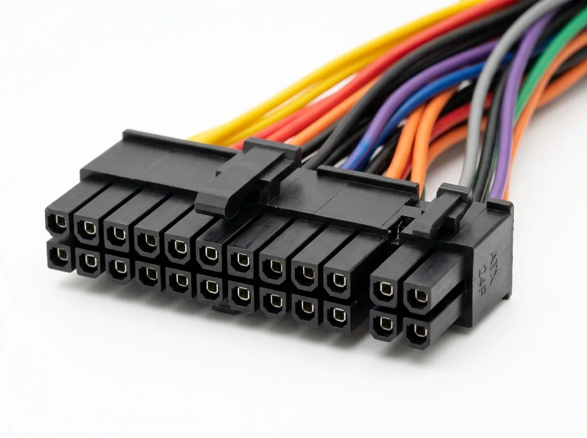
It carries several distinct voltages at once, which is why the connector is so wide. Each pin is tied to a specific rail, and the motherboard depends on all of them being present and stable. In older designs the board pulled heavier current directly from this connector, so the number of pins carrying each voltage matters.
The voltages you'll find here are the standard ATX rails. You don't need to memorize the full pinout for the exam, but you should recognize which rails exist and what a few key signal pins do.
| Rail or signal | Purpose |
|---|---|
| +3.3 V | Low-voltage logic, some RAM and chipset circuits |
| +5 V | Legacy logic, USB, drives on older designs |
| +12 V | Main high-power rail for CPU and PCIe on modern boards |
| −12 V | Legacy serial ports, rarely used today |
| +5 VSB | Standby power, keeps board alive while "off" |
| PS_ON | Signal that tells the PSU to turn on |
| PWR_OK | Signal telling the board the rails are stable |
Two of those signals are worth understanding because they explain common failures. The +5 V standby rail (+5VSB) stays powered whenever the PSU is plugged in and switched on at the back, even when the computer is "off." That's what lets a wake-on-LAN packet or a front-panel power button start the machine. The PS_ON signal is what the power button ultimately triggers, telling the PSU to bring up its main rails. The PWR_OK (also called Power Good) signal tells the board the voltages are within range so it's safe to start. A failing PSU that produces power but never asserts PWR_OK can cause a system that won't boot even though fans spin.
The connector grew from 20 pins to 24 as boards demanded more power
The original ATX standard used a 20-pin main connector.